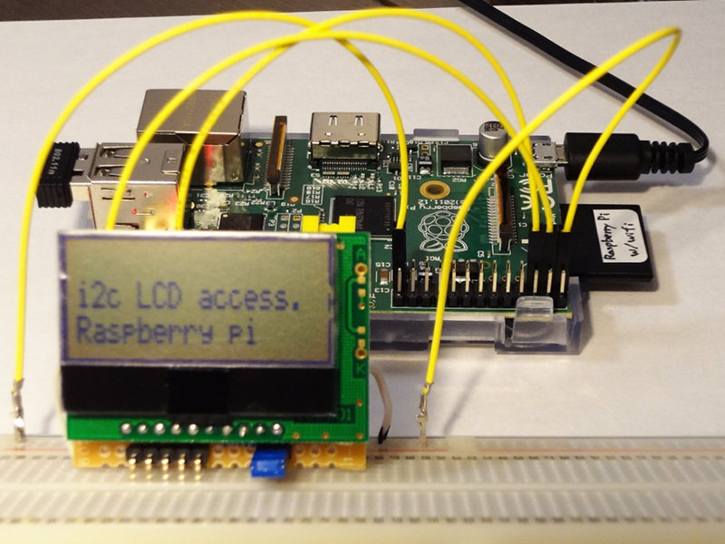
Raspberry piにStrawberry Linuxの「I2C低電圧キャラクタ液晶モジュール(16x2行) SB1602B」を接続して利用する方法
■ i2cドライバを有効にする
ドライバを追加する
/etc/modules
snd-bcm2835
i2c-dev ← この行を追加
さらに、ブラックリストから削除する
/etc/modprobe.d/raspi-blacklist.conf
# blacklist spi and i2c by default (many users don't need them)
blacklist spi-bcm2708
#blacklist i2c-bcm2708 ← この行をコメントアウト
上記の設定後Raspberry piを再起動
■ i2cツールのインストール
$ sudo apt-get install i2c-tools
LCDのアドレスを調べる
$ sudo i2cdetect -y 0
0 1 2 3 4 5 6 7 8 9 a b c d e f
00: -- -- -- -- -- -- -- -- -- -- -- -- --
10: -- -- -- -- -- -- -- -- -- -- -- -- -- -- -- --
20: -- -- -- -- -- -- -- -- -- -- -- -- -- -- -- --
30: -- -- -- -- -- -- -- -- -- -- -- -- -- -- -- --
40: -- -- -- -- -- -- -- -- -- -- -- -- -- -- -- --
50: -- -- -- -- -- -- -- -- -- -- -- -- -- -- -- --
60: -- -- -- -- -- -- -- -- -- -- -- -- -- -- -- --
70: -- -- -- -- -- -- -- --
$ sudo i2cdetect -y 1
0 1 2 3 4 5 6 7 8 9 a b c d e f
00: -- -- -- -- -- -- -- -- -- -- -- -- --
10: -- -- -- -- -- -- -- -- -- -- -- -- -- -- -- --
20: -- -- -- -- -- -- -- -- -- -- -- -- -- -- -- --
30: -- -- -- -- -- -- -- -- -- -- -- -- -- -- 3e --
40: -- -- -- -- -- -- -- -- -- -- -- -- -- -- -- --
50: -- -- -- -- -- -- -- -- -- -- -- -- -- -- -- --
60: -- -- -- -- -- -- -- -- -- -- -- -- -- -- -- --
70: -- -- -- -- -- -- -- --
チャンネル1(/dev/i2c-1)のアドレス0x3eに接続されているのがわかった。
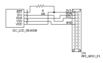
■ 回路図
Raspberry piのGPIO P1ポートのピン配置は「RPi Low-level peripherals」を参考にした。なお、Rpiのi2cポートはプルアップされているため、ユーザ側でプルアップ抵抗を用意する必要は無い。

なお、LCD側のRST端子とVDD(3.3V)端子を10kの抵抗で接続してプルアップしている(0Vにするとリセットされるため)。
■ シェルスクリプトで利用する場合
「Raspberry PiにI2C液晶をつける」のスクリプトを丸ごとコピーした
i2c_lcd.sh
#!/bin/bash
function usage {
echo "Usage: $0 [-ic] [-p pos] message" > /dev/stderr;
echo " -i : LCD init, -c : Clear Screen" > /dev/stderr
echo " -p : position (0:top left, 40:bottom left)" > /dev/stderr
exit 1
}
[ $# = 0 ] && usage
while getopts "icp:" flag; do
case $flag in
\?) usage ;;
i) i2cset -y 1 0x3e 0 0x38 0x39 0x14 0x78 0x5e 0x6c i
sleep 0.25
i2cset -y 1 0x3e 0 0x0c 0x01 0x06 i
sleep 0.05
;;
c) i2cset -y 1 0x3e 0 0x01 ;;
p) i2cset -y 1 0x3e 0 $((OPTARG+128)) ;;
esac
done
shift $((OPTIND-1))
[ $# = 0 ] && exit
LANG=C
MSG=`echo -n "$1" | perl -pe '$_=join" ",map{ord }split//'`
#echo $MSG
i2cset -y 1 0x3e 0x40 $MSG i
このスクリプトをroot権限で次のように実行する
$ sudo ./i2c_lcd.sh -i "i2c test program"
$ sudo ./i2c_lcd.sh -p 40 "Raspberry pi"
または、piをi2cグループに追加すれば、ユーザ権限で実行可能になる。
$ sudo adduser pi i2c
■ C言語で利用する場合
「Raspberry Pi で I2C その2 ストリナI2C LCD」のソースコードを丸ごとコピーした。
i2c_lcd.c
#include <stdio.h>
#include <stdlib.h>
#include <time.h>
#include <unistd.h>
#include <linux/i2c-dev.h>
#include <fcntl.h>
#include <sys/ioctl.h>
#define LCD_ADDRESS (0b0111110)
#define LCD_CONTRAST 100
#define LCD_RS_CMD (0x00)
#define LCD_RS_DATA (0x40)
#define LCD_CMD_CLEAR (0x01)
#define LCD_CMD_HOME (0x03)
// 関数プロトタイプ宣言。
void LCD_init(int fd);
void LCD_write(unsigned char rs, unsigned char data, int fd);
void LCD_clear(int fd);
void LCD_setCursor(unsigned char col, unsigned char row, int fd);
void LCD_putc(unsigned char c, int fd);
void LCD_puts(char *str, int fd);
int main(int argc, char **argv){
int lcd; // ファイルディスクリプタ。
char *i2cFileName = "/dev/i2c-1"; // I2Cドライバファイル名。
int lcdAddress = LCD_ADDRESS; // I2C LCD のアドレス。
printf("***** start i2c lcd test program *****\n");
// I2CポートをRead/Write属性でオープン。
if ((lcd = open(i2cFileName, O_RDWR)) < 0){
printf("Faild to open i2c port\n");
exit(1);
}
// 通信先アドレスの設定。
if (ioctl(lcd, I2C_SLAVE, lcdAddress) < 0){
printf("Unable to get bus access to talk to slave\n");
exit(1);
}
usleep(100*1000); // 100ミリ秒
// LCD初期化。
LCD_init(lcd);
// メッセージ表示。
LCD_setCursor(0, 0, lcd);
LCD_puts("i2c LCD access.", lcd);
LCD_setCursor(0, 1, lcd);
LCD_puts("Raspberry pi", lcd);
return 0;
}
void LCD_init(int fd){
usleep(40*1000); // 40ミリ秒
// ST7032 Initial Program Code Example For 8051 MPU(8 Bit Interface) の初期化サンプルの通り
// Function Set : 8bit bus mode, 2-line mode,normal font,normal instruction mode
LCD_write(LCD_RS_CMD, 0b00111000, fd); // 0x38
// Function Set : extension instruction mode
LCD_write(LCD_RS_CMD, 0b00111001, fd); // 0x39
// Internal OSC frequency(extension instruction mode)
LCD_write(LCD_RS_CMD, 0b00010100, fd); // 0x14
// Contrast set(extension instruction mode) コントラスト値下位4bit設定
LCD_write(LCD_RS_CMD, 0b01110000 | (LCD_CONTRAST & 0xF), fd); // 0x78 = 0x70 + 0x8
// Power/ICON/Contrast set(extension instruction mode) コントラスト値上位2bit設定
LCD_write(LCD_RS_CMD, 0b01011100 | ((LCD_CONTRAST >> 4) & 0x3), fd); // 0x5c + 0
// Follower control。internal follower on,
LCD_write(LCD_RS_CMD, 0b01101100, fd); // 0x6c
usleep(300*1000); // 300ミリ秒
// Function Set。normal instruction mode。
// LCD_write(LCD_RS_CMD, 0b00111000, fd); // 0x38
// Display On
LCD_write(LCD_RS_CMD, 0b00001100, fd); // 0x0c
// Clear Display
LCD_write(LCD_RS_CMD, 0b00000001, fd); // 0x01
// Entry Mode Set
LCD_write(LCD_RS_CMD, 0b00000110, fd); // 0x06
// 時間待ち。
usleep(2*1000);
}
void LCD_write(unsigned char rs, unsigned char data, int fd)
{
unsigned char buf[2];
if (rs == LCD_RS_CMD || rs == LCD_RS_DATA){
// LCD_RS_CMD ならコマンドモード。LCD_RS_DATA ならデータモード。
buf[0] = rs;
buf[1] = data;
if (write(fd, buf, 2) != 2){
printf("Error writeing to i2c slave1\n");
}
}
else{
// rsの指定がLCD_RS_CMD,LCD_RS_DATA以外ならなにもしない。
}
}
void LCD_clear(int fd)
{
LCD_write(LCD_RS_CMD, LCD_CMD_CLEAR, fd);
usleep(2*1000);
LCD_write(LCD_RS_CMD, LCD_CMD_HOME, fd);
usleep(2*1000);
}
void LCD_setCursor(unsigned char col, unsigned char row, int fd)
{
unsigned char offset[] = {0x00, 0x40};
if (row > 1) row = 1;
if (col > 16) col = 16;
LCD_write(LCD_RS_CMD, 0x80 | (col + offset[row]), fd);
}
void LCD_putc(unsigned char c, int fd)
{
LCD_write(LCD_RS_DATA, c, fd);
}
void LCD_puts(char *str, int fd)
{
int i;
for (i = 0; i < 16; i++){
if (str[i] == 0x00){
break;
}
else{
LCD_putc((unsigned int)str[i], fd);
}
}
}
このソースコードをコンパイルしてroot権限で実行
$ gcc i2c_lcd.c -lrt
$ sudo ./a.out
