中国の電材商社から、NE555タイマICを使った可変周波数・デューテーサイクル発振回路キットを購入した。

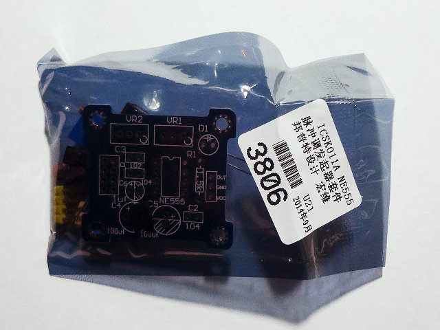
送料込み200円程度なので、部品を日本でかき集めるより遥かに安くお手軽だ。送られてきたのは、プリント基板と部品。 写真では、組みあがり品のように見えたのだが… 。 実際には基板と部品が袋に入って配送されてきた。
| 名称 | 個数 |
|---|---|
| NE555 | 1 |
| 8pin ICソケット | 1 |
| 炭素皮膜抵抗 1.5k | 1 |
| 多回転半固定抵抗 10k | 2 |
| セラミックコンデンサ 104 | 2 |
| セラミックコンデンサ 102 | 1 |
| 電解コンデンサ 50V 100uF | 2 |
| 電解コンデンサ 50V 1uF | 1 |
| LED 5mm 赤 | 1 |
| ヘッダピン4pin*2, 3pin*1 | 1式 |
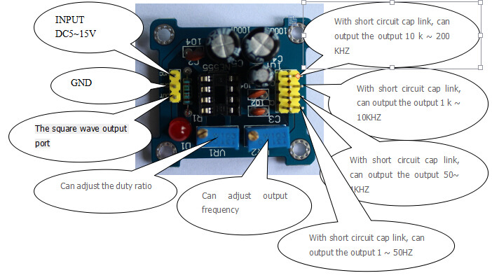
商社によれば、製品の仕様はこんな感じで、これに従って部品を検品して組み立てる。
Ⅰ. That principle
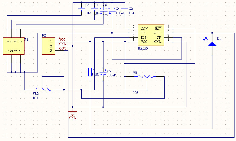
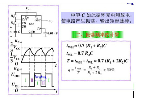
The multivibrator composed of 555 timer, and waveform as shown in figure
After turning on the power supply, power supply VDD through R1 and R2 for capacitance C charging, when Uc < 1/3 VDD, oscillator output Vo = 1, discharge tube.After the Uc charge to 2/3 or more VDD, oscillator output Vo flip to 0, the discharge tube conduction, make the discharge end (DIS) grounding, capacitance C through R2 to discharge, bring down the Uc.When reduced to a third or less VDD Uc, oscillator output Vo and flip into 1, discharge tube and as of right now, make the discharge end (DIS) not grounding, power VDD through R1 and R2 and recharging the capacitance C, made up from a third VDD Uc two-thirds VDD, trigger and flip, so the cycle, so as to get continuous variation on the output side Vo oscillation pulse waveform.Pulse width 0.7 R2C TL material, determined by the capacitance C discharge time;TH = 0.7 (R1 + R2) C, is determined by capacitance C charging time, pulse period T material TH + TL
Ⅱ. Directions for use
1.The input voltage: DC5 ~ 12 v.The amplitude in: 4.2 V to 11.4 V
2.The function and operation:
■ 測定
部品をPCBにはんだ付けしてから、オシロスコープに接続して測定してみる。
商社のホームページに表示されていたジャンパ位置と周波数の対応が全く逆だった以外は、まあ、想定通り
ジャンパ位置と、それぞれで出力可能な発振周波数
| ジャンパ位置 | 発振可能周波数 |
|---|---|
| 1 : 0.001uF (最上段) | 65 kHz 〜 1.2 Mhz以上 |
| 2 : 0.1uF | 1.4 kHz 〜 68 kHz |
| 3 : 1uF | 50 Hz 〜 3.6 kHz |
| 4 : 100uF (最下段) | 1 Hz ? 〜 34 Hz |
最大周波数が 1.2Mhz以上となっているのは、保有している10Mhzサンプリングのオシロスコープで測定不能領域に突入したため。
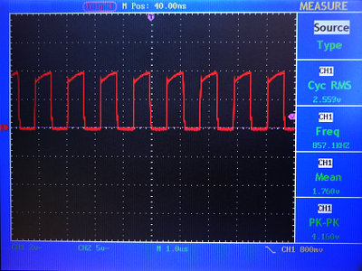
ジャンパ位置1で波形がそれなりに使えそうだった最大周波数付近(800kHz)
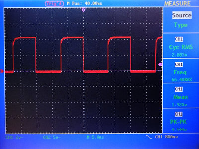
ジャンパ位置1、60kHz付近
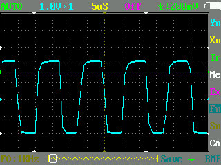
ジャンパ位置1、80kHz付近
ポケットオシロ DSO201(1MHzサンプリング機)ではこのあたりが限界。波形はグチャグチャだが、周波数程度までなら読み取れる
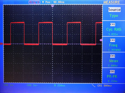
ジャンパ位置2、1.4kHz付近
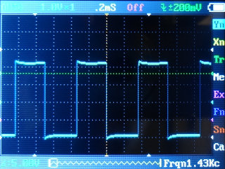
ジャンパ位置2、1.4kHz付近 (ポケットオシロの表示は、かなりまとも)
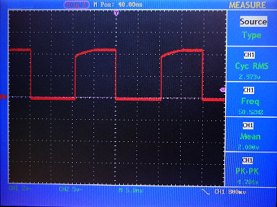
ジャンパ位置3、50Hz付近
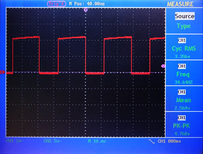
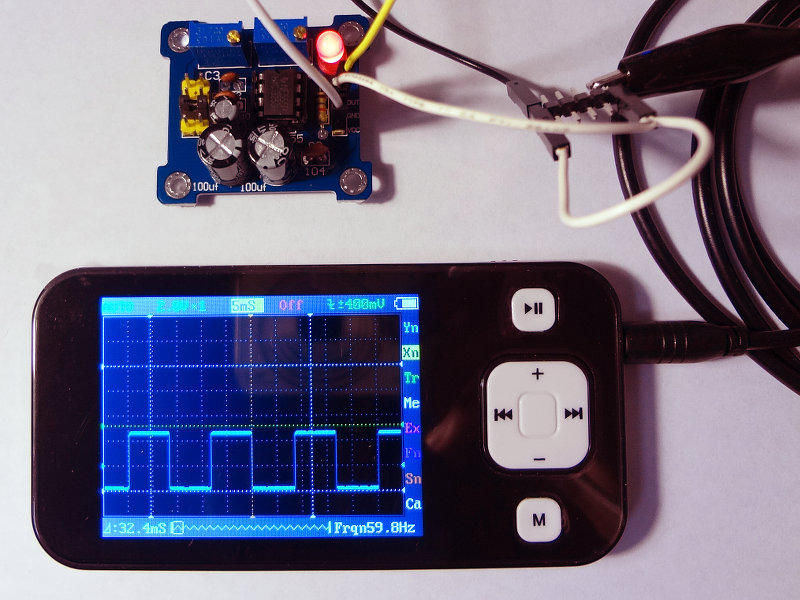
ジャンパ位置4、30Hz付近
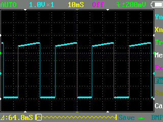
ジャンパ位置4、30Hz付近 (ポケットオシロの表示)
